These entries will comprise work on concept art and asset creation. Material will be created with 3ds Max and Vue. The objective of this study is to successfully design and visualize a fictitious research facility that is based in the U.S. Southwest, and to export assets to the Unreal game engine.
8/26/2014
I began by considering the role of these buildings as well as the potential context. Whether this existed at White Sands (for the short film) or elsewhere, the larger context would still be the U.S. Southwest. With this in mind I started with generic shapes and forms (1). I tried basic geometric forms and then created something with a bit of complexity (2), and then refined that further. I had originally intended to make something more organic and sculptural, as seen in row 3. My immediate concern was the fact that if this was built-in the middle of nowhere, it probably would not make much sense to hire expensive designers to create something that was no benefit to any urban context. Also, if we are talking about a research facility, it would probably be nondescript. On the other hand, we are talking about a film and people like to see cool things in films. Also, if we consider the fact that research requires funding and grants to survive, having a building that represented the forward-thinking station of the work would be a good thing for visiting bureaucrats, CEOs and legislators to see and experience first hand. In other words, it would contribute to the image of the research company and the work being done. In the case of the film, the research focuses on new forms of life and associated artifacts. While the facility is not a secret, the extent to which they probe the depths of the unknown is largely hidden from the public.

Planned for the short film is an establishing aerial shot of flight over dunes. As we go over a final dune the facility comes into view. This will be the only time the audience sees the structure, so it needs to have some kind of visual impact yet be believable in its appearance. I am hoping to try rendering this with Vue xStream, which enables the use of Vue directly in Max or Maya. I think it leaves a watermark on images rendered in the student version. We’ll see. There is also still the option of combining something old with something new. I am still thinking about that. Below is a variation on 2, above. I cleaned it up a bit, got rid of some unneccessary lines. I had originally planned on having sections of grass near the entrances but then I thought better of it an opted for xeriscaping. Of course, things change, but we often buildings in the Southwest surrounded by grass, using much water, when we can make really beautiful arrangements with xeriscaping.
 I have not yet made a final decision on a design.
8/31
This weekend I spent some time investigating camera tracking software, specifically one called SynthEyes:
http://www.ssontech.com/synovu.htm
What I would like to do at some point is take the structure that is being designed, or part of it, and composite that with actual live footage. Motion tracking is pretty easy in After Effects but I want to try importing the camera data into 3ds Max, render the structure, shadows and diffuse light and then composite them with the footage. However, SynthEyes costs money, even for the education version. Perhaps I could try the demo version. I have also asked Brad about what he uses for his advanced Maya class. In any event, it’s just an idea at this point.
Update: Brad informs me that in his advanced Maya class they do not use camera tracing but rather camera mapping, which is different from my needs. So, I will have to research what is out there when I have time.
9/1
I have not been satisfied with the ideas thus far. The forms are generally too clunky and heavy-handed. It would be easy to take the shapes from the above image and import the paths into Max and put some materials on them, but that would not pose any sort of challenge. I already have work that looks like that in my portfolio, although I am still interested in the xeriscaping idea. If you look at number 3, in the first image, a design like this offers more challenge in creating. It has a combination of curves and angular forms. So, with this in mind I have created some new top-down forms, below:
(Updated 9/9)

These are much more interesting, I think. My goal in creating these was to contrast a more fluid, organic design (as you see a the ends) with very clean and pure shapes (as seen in the middle). As with the clunky design (Number 2) I imagine a lobby area, something akin to a museum, in the front (the left organic shape, above), the research area in the utilitarian space in the middle, and the administrative area on the right.

Above is a second, similar idea, but in a different form. I imagine the gradient areas as using tinted glass or some other type of transparent building material. Regarding the colors, specifically yellow, that is solely for showing the various forms and how they fit together in these images. Having said that, I am curious in experimenting with bold colors here and there in the actual render. Obviously it depends on the real-world context. I have often imagined architecture in unusual colors. It seems like we make structures with glass and concrete, and then occasionally color them with light. That makes sense, but I would like to see something different, as if the colors in these images (or other colors) were actually part of the design. The flip side to this idea is that often, designs that look great on paper look pretty bad in the real world. Whether it is the design, itself, or the colors, it usually seems like muted shades are the safest for fitting into an existing context. I have seen brightly colored buildings in Asia and in South America and, while they often look decent after construction, the buildings look really bad and garish once the dirt and grime of urban areas begin to tarnish the facades and clutter the grounds.
Below is a third image from this series. This one is a bit simplified in that is has one organic area on the left and then the research area on the right. Of course, these designs are arbitrary in their physical shape with regard to physical context. As for the profile of these structures, I imagine something straight and vertical. Still, nothing is final. I like the direction of these new designs and I think I will increase my focus on one, then simplify it and work out the details so I can move on to the next step. It strikes me that we are already in September now so I need to keep the final design relatively simple. Next week is asset and material research. After that I have three weeks of modelling scheduled.

9/9
For this week I needed to make sure that material are in order, which was actually really easy. I have some materials from Dosch Design. Also, I know how to make tile-able materials quite easily so I can essentially make whatever I need. As for other assets, Turbosquid has many free assets such as desks, chairs and other odds and ends. Foliage is a different matter, as my goal is to use Vue. I am not sure about using indoor/decorative plants, yet. A lot of it depends on how the interior shapes up. Much of the work I have been attracted to is rather spacious (for the entry area), with concrete on one side and a lot of glass on the other. There will be slowly rising stairs, in an arc, against the wall that leads to an exhibit area above, that is actually a loft, from which you can see below into the lobby. I will model the building as needed, completed with some particulars for interior design, and then I will use pre-made assets for various other items. Ideally I would model everything, but I simply won’t have time to model a bunch of furniture, desk, chairs, extra lighting systems, etc. I’ll do what I can. The other issue is complexity. Given that this needs to be exportable into Unreal, it can not be overly complicated.This week I am also brushing up on my modeling skills, as it’s been quite some time since I have used 3ds Max. I spent all day yesterday, as well as today, going over this. I see that a lot has changed. There is now a Graphite ribbon editor for polygon and subdivision surface modelling. I think what I will do is prepare the basic forms in Illustrator, in millimeters, so that it can be scaled correctly in Max. This is important because it will need to be the right size not only for materials and for rendering the environment, but also for exporting it to Unreal. So, although I will get started this week (preparing the basic shapes tonight), I won’t really have much of anything to show until next week. I do not anticipate any problems at this point.These are some of the tutorials I have been looking at:
9/16
I finally began modelling this week.
The general form can be seen above. The idea is that visitors would enter, go through the lobby, loop back around under the 2nd floor exhibit area, go through the 1st floor exhibit area, and then up gently sloping stairs that hug the inside of the center wall, taking them to the 2nd floor exhibit area. Each story is four meters, with the 2nd floor exhibit area having a higher ceiling as it occupies the top two stories. Below you can see the same area from the reverse angle.
This first area of the building, as well as the facade, are my main areas of concern. The research area would actually be pretty mundane and functional. It’s important, and I’ll do what I can, but it is not as interesting as entry and exhibit area.
I am slowly getting back into familiar territory with 3ds Max. I used paths exported from Illustrator to create the basic shapes. One of the things I learned is that, in order to have accurate measurements, the use of the XForm modifier in the Modifier Stack is required before using the scale gizmo. Otherwise, objects will be scaled but the units will be wrong. Also, when extrude is used, it will be at the wrong size. One anomaly I ran into was the fact that the length of the building was in meters (Select object/Utilities/Measure), but the height was in tenths of meters. In other words, placing the second floor 4 meters up meant typing in .4 meters. Actually I am going to go back and investigate how the units work right after this. The next issue I had was using soft selection to taper the front of the building. The problem was that, as I scaled, the selection cause some of the bottom vertices to go below the floor. What I should have done was select some of the top edges, with soft select, and then transposed them either through rotation or by moving. Now that I think about it, the best way would probably have been to move the anchor of the rotate gizmo and try that. In any event, all I had to do was select all the bottom vertices and then align them using the graphite ribbon. I also realized I put in wrong information in my sketches. I had the height as 36 meters. It is actually 12 meters, with each storey being 4 meters. In Max, every time I tried to use the extrude modifier, I made it 36 meters, which was too much. I finally realized my mistake and corrected the graphic.
I have some additional instructional material from Gnomon that I will be taking a look at tonight. I know specifically what I want to do for the outer walls, but I need to look at the best ways for cutting geometry, and figure out whether or not to use Booleans for some of the shapes I want. I am taking light into account throughout the design of this buildings, so there will be areas of glass alternating with the other wall materials so that natural light may help create the atmosphere. The idea is to have open, uncluttered spaces that are given character by the light.
9/23
Today I continued modeling. Specifically what I did was begin to divide the walls into sections based on what would be glass or not. Essentially this involves using vertex subobject mode and Cut (from the Command Panel) to strategically connect vertices with new edges. Then I would select the area I wanted using polygon subobject mode, detach the geometry and then clean up whatever broken edges with the bridge function. Doing this is simultaneously tedious and fun, if that is possible. Before this I experimented with different ways of achieving what I wanted. I tried using boolean operations for some of the angled shapes on the right side of the facade, but that was not very intuitive. I ended up creating paths in Illustrator, exporting them and then extruding them in 3ds. I ran into an issue, however, and that is scale. As with before I should have used XForm in the modifier stack but when I did and then tried to convert the splines to editable poly, they would disappear. I searched for info and all I could find was the suggestion that perhaps the splines were too complex. Either way, I got it to work.
I also began adding slight detail to the exterior, nothing worth uploading at this point, however. I think what I will do for the large sections of glass is simply add support structures in certain places within the glass objects. This will save some valuable time, I think, as opposed to creating many individual sections of glass. We’ll see how it goes. This is a reminder of the difference between designing concept art and geometry for a game engine; it needs to be simple for the latter.
Also, we talked about some of the images that I like, so I have uploaded some here.
Below is one of the images I mentioned in our last meeting. I like the way it looks but my concern is that all of the intricate shadows would distract from the exhibit area. I’ll experiment with it. I just think the combination of these lighting effects with concrete and glass in a larger space will look nice. We’ll see.
One of the things I like about a lot of these structures is that they have an interesting shape contrasted by simple exteriors/textures.
I really like the image below, and I wanted to create something like this for this project, but it seemed a bit lean on space for research. On the other hand, this was how I imagined my structure fitting into an urban environment. You can see it there, but it has its own space so it does not get drowned in the background of other buildings. Still, though, I like the idea of having mine out in the middle of nowhere. Hopefully with Vue I’ll be able to try different environments.
I really like the following three, and they match the idea of interesting buildings in more remote areas. I like the simplicity of the design and I can actually see something similar to this for far side (the straight side) of my structure.
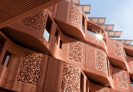
I like these pattern/screen sections.
Below is where I imagined the location, at White Sands.

Finally this is the image by Zaha Hadid that I mentioned.
I have tons of images like these. Like I said, I collect them quite frequently. The next step is to continue the model. Hopefully in two or three weeks I’ll be ready to move on to materials.
10/13
OK, back from Fall break. I looked at more work for inspiration and, while I found many great-looking things, I am glad I kept this relatively simple. I spent all day experimenting with lights and materials. Before that, however, I had to tighten up some of the geometry. There were seams here and there that did not match. Also, I discovered I had quite a few flipped normals. I only discovered that after using the Slate Material editor to apply materials. Some objects that appeared as one would expect in the viewport rendered black. I also discovered some holes in the geometry that I closed by going into edge subobject mode and bridging.
I am mostly using the architectural materials built into 3ds, although I may be adding some bitmaps in the diffuse channel at some point. As I mentioned, I am glad I kept this simple because the look I am going for, with a black reflective dividing wall by the stairs, is pretty huge. If the space was cluttered with too many other objects then it would be too busy. Tonight and tomorrow I will explore osme more lighting attributes. I also think I will design a couple couches.
Although things are going well, my main concern is whether to do more detail work and populating the environment now, or after I get the basic structure in Unreal Engine 4. Speaking of which, last night I took a look at Unreal Engine 4. There is a licensing agreement for $20/month, but free of charge for students. Although I have never used Unreal before, it looks fantastic and I can’t wait to start learning about importing this structure. Actually, this is another reason why I want to keep it simple; I have no idea how much work dealing with UV mapping will be required. I’m learning what is possible in a short amount of time as I go along.

Above you can see that the stairs are black. Although I wanted to experiment with colors, this was actually due to flipped normals in the banister geometry. To fix this you select Views>xView>Face Orientation. Whatever is green is flipped. Go into polygon subobject mode, select the green polygons, then go into your stack, Edit Polygons, and press the Flip button. Below you can see the strange, glassy black texture of the black dividing wall. I used a slight bump map to create unusual reflections of the surrounding environment. The red you see is one of the lights. I played with the lighting colors not because I want colors, but just to get a different contextual view of how things were fitting together.

Below is a view from the second floor, looking down towards the stairs. You can see how the open areas contrast with their own reflections in the black glass. The lights are simple target spotlights.

I like the above render, it’s OK. The problem is that the reddish wall around the edge of the floor is supposed to be glass. It was not rendering correctly, but I got it sorted. Another strange anomaly was the fact that the first few renders each took quite some time. Then, inexplicably, the render weres light-speed and only took about 2 seconds. Strange.

Above and below are similar shots. The idea is to have this general ambiance, with extra lights only to highlight individual exhibits. I think I mat try to create an inset edge extruded into the ceiling. Right now the floor is, as mentioned, a basic architectural material, but I might experiment with some type of carpet. My experience, though, has led me to value more simple design, in general.
The stairs lead to the 2nd floor, up and to the left, where visitors will see the centerpiece, a creature I am designing in Swardson’s independent study.

I removed the ceiling for this one. You can see here that the lights are blown out. I’ll make the lights more accurate once I see how daylight from Vue impacts the interior.

In the image below I did a brief experiment with depth of field. Now might be a good time to mention that these renders are done with the regular scanline renderer and not Mental Ray. I think I’ll switch to MR once I get Vue sorted, and that will enable more control over DoF, f-stops, global illumination, exposure control and all of that other great stuff. Right now the scene is lit with standard lights but I’ll change them to photometric and make the proper adjustments in the near future. In the meantime I am going over these topics with some Lynda videos.

OK so Vue is not working out very well. I can use it, it’s integrated pretty well, but it has watermarks all over every inch of each render. It looks horrible and I don’t want to turn anything in like that. I’ll see what I can make for an environment right within Max. It’s a shame because it has so much potential yet it dissuades one from using it. Seriously, what is the point of making nice images only to have them destroyed by a watermark? What they should do is allow renders up to 1280 x 720 resolution, for example, with no watermarks.
10/18
I just found out that the demo of V Ray costs $35. Well, we know it looks great, anyway. I am going to look for further options, such as Lux and Corona.
–
–
–
–
–
–
–
–
–
–
–
–
–
–
–
–
–
10-22
I’ve been working this for another two days and I have these renders using the default scanline renderer. To begin with, here is a diagram of the flow of the experience:

As visitors approach they can get an enticing hint of what lies inside by seeing through the glass as they approach, but that is taken away upon entrance (1).Visitors would enter on the ground floor. This is a space that acts as counterpoint with the low, small entry area contrasted with larger area revealed inside. Turning right reveals the first exhibit area (2). Going further through the space reveals the first small display exhibits in glass. This leads to the first major exhibit in the far left. Visitors would then follow the wall back to the right (3), where they will be given more specific information. Once again visitors will turn around, now with the stairs on their left. This path reveals even larger exhibits of more compelling artifacts as they approach the bottom of the stairs. Going up the stairs, visitors will be shown plaques of information on the black glass dividing wall. As visitors reach the top of the stairs and turn left, they see the centerpiece of the exhibit (4).

Above, the latter part of area 2. In the fore and midground you see the first display cases. They are empty because the artifacts for them are yet to be designed. In the background is a rendition of an area located by a probe. This, as well as other visuals here, are also on the company’s web site, serving to enhance the lore of the world and the story. The glass wall on the left is reflecting the art on the wall. One thing I appreciate about design and film is the notion that choices should be specifically motivated rather than arbitrary. If the camera moves there is a reason. Likewise if the wall is black glass, there is a reason. As you see here and will see in later images, the wall distorts its surroundings in the reflection. I used a large-scale bump map to accomplish this, the reason being that the reality we take for granted is being distorted by these new discoveries and insights.

Above is the view in area 3. If you look closely at the far right you will see the right display exhibit from the preceding image. You can also see the aforementioned distortions in the black glass. Moving into the background are more glass exhibits, increasing in size and interest. Imagine looking into this room from the opening on the far right. This opening is what is seen, previously mentioned, from the outside, through the glass. When visitors reach this area, it completes the circuit of denial and reward. The wall on the left features imagery similar to that of the first exhibit area. The black shape on the left near the floor is a bench. If this shot was your POV, you would be standing right in front of the first main exhibit.

Above is the same space, seen from the opposite direction. The glass object in the very back is the first main exhibit. Each of these large exhibits has its own light in addition to the ambient light. I have not actually added light fixtures at this point. If you pivot to the right you would see the image below:
I have created some sloped exhibits that provide info to visitors. Above this particular one you can see a large image rising towards the ceiling. This is essentially a large information graphic that describes what the company has figured out to this point. You may see the actual
infographic here. This is a very large design, hence its location; you can see it from the ground floor or from the second floor.
After viewing the larger glass exhibits you go up the stairs, seen above. This takes visitors to area 4, below.
It does not look like much now, but that is because it is missing the main attraction:
A creature such as the ones above will appear, fossilized and in pieces in area 4. Another image I used is one trapped in amber, below:

OK so where are we in this project? I still have not created the outside world. That is not as important as the rest of this, at least for my needs. I had to make a choice between doing that or doing the interior. I am sure that Vue is great under the right circumstances but waiting forever for final-quality renders of images I don’t need that are covered with ugly watermarks made it an easy decision. Also, as mentioned, V-Ray is 35 shekels just for the demo. Another issue I face is the fact that next week is the end of October which, according to the schedule, does not leave much time (one day, not including rendering in Mental Ray) for experimenting with other renderers. I should be transitioning to Unreal at that point. This is especially true given that using other renderers requires further research and possibly changing scene materials. In fact I have yet to render with Mental Ray, which will require, at the least, switching to photometric lights and making adjustments there. Here are the options as I see it at the moment:
1. Spend two or three more weeks using another renderer, thereby removing time for Unreal.
2. Skip Unreal and use other renderers.
3. Skip other renderers and go straight to Unreal.
Another thing to keep in mind is that I have never used Unreal Engine before. That will require research and gaining familiarity. Given that working with Unreal is important to some of the work I want to do, I recommend focusing on that. I know that is important to ARTS. It would also, importantly, provide new information, whereas we already know V-Ray looks good. I am leaning towards option 3.
–
–
10/28
Now that I have the basic locations for each exhibit I want to revisit the lighting. Up to this point I have been using simple, standard lights with the scanline renderer. This has enabled me to see where things should go and even get some good looks with the renders. It has also enabled me to quickly experiment with light locations while working with the flow of the building. I have been using both Standard and Architectural materials. With Mental Ray, however, I will be switching to Arch + Design materials. This should result in better, more accurate diffuse light/indirect illumination and other things such as refraction effects, as well as transparency and translucency control, and of course indirect illumination through Final Gather and ambient occlusion.
–
I have taken the initiative to get some basic information about indoor lighting for exhibit areas. What I have gleaned thus far is that the ambient light should be no more than half the brightness of the direct lighting for each exhibit piece, or the combined exhibit pieces in an area of shared ambient diffuse light. This is really only possible with photometric lights that will enable me to look at the Kelvin value of each light, as the Multiplier value for Standard lights don’t have any real-world metrics for comparison. Of course the materials make an impact here, as well. For example, more light sources means more reflection and refraction from the glass of each exhibit. The Photographic Exposure Control (Environment and Effects panel from the rendered image panel) will offer fine controls over white point, contrast, etc. I have downloaded some IES (Illuminating Engineering Society) files that provide a wide variety of realistic templates for individual light sources. Below is an image included with the download that shows thirty types:

These lights go in the Scene Assets\Photometric folder within the project folder and can be called after placing a photometric light into the scene. If you parent the light to the fixture you can then have more realistic control over the light’s behavior. I have no idea who authored these lights, otherwise I would give credit. As you can see, they all have different falloff rates and distribution types, and should be useful.
–
Another word on materials. I do not yet know the extent to which materials can be imported, along with object meshes, into Unreal Engine 4. I have begun to look for some introductory training but in reality I have spent the last couple of days looking at Lynda videos for Mental Ray. I have found various videos by
Aaron F. Ross to be highly enlightening and useful. In any event, I may have to redo the materials yet again in Unreal Engine 4.
–
Going back to the general issue of lighting, three other factors must be taken into account. First, the view of artifacts from ground level as well as from above. Larger glass cases are placed strategically near the edge of the second floor so that visitors may look down on larger artifacts, as well as seeing them from the first floor. Second, the nature of each artifact will determine the necessity and nature of three-way subject lighting, in turn effecting the relationship with the ambient diffuse light. Lastly, there is the matter of daylight. Now that I will be using photometric lighting, daylight will finally become a factor, with MR Sky and MR Sky Portal. Daylight will, in one section, contribute to the ambient light that should not directly compete with the direct exhibit lights. This is especially true in the first exhibit area. All of this together will be tweaked with exposure control, white point and image control in the Environment and Effects panel. I can also add a background using a cylindrical environment with a Self-Illumination map in the Material Editor.
–
As mentioned before, I wish I had more time. I love this type of work and I especially look forward to using Unreal Engine 4, even though it is $20/month. I am not only designing and building the space but the objects that go into the space, as well. I would like a larger object to hang from the ceiling, and I had also considered the possibility for having an object embedded into the floor, under a glass panel, seen from the second floor. I will most likely have to design most of the artifacts after the semester is finished, as my final month in Swardson’s study is being used for different concept art.
10/31
Today I switched to Mental Ray and began changing the lights. The scene below is a test render using a single 100W light at 3200 Kelvin. I used manual exposure controls: .06 shutter speed, f-stop 4, 400 ISO. In other words, this uses a wide aperture and short speed. The grain is cause by low final gather and image precision settings.
This one has two identical lights:
The image below has the same two lights, which are photometric free lights, each at 2400 Kelvin:
I have been looking at more images of similar interiors. I may try hanging multiple smaller lights from the ceiling so that there is diffuse light from multiple angles. In that case it might be good to move the glass displays towards the middle of the floor. My concern with hanging lights would be that their cables might obstruct views of the larger pieces on the walls.
11/2
Below is a render with photometric lights. There are two free lights on either end, one behind the camera, and five target lights. It took perhaps 3 hours or so to render with medium image precision, medium soft shadows and medium final gather.

 I have not yet made a final decision on a design.


 The image below I like because of the light. It has a very cool feeling to it, like I can almost feel the air in this image.


 I removed the ceiling for this one. You can see here that the lights are blown out. I’ll make the lights more accurate once I see how daylight from Vue impacts the interior.


